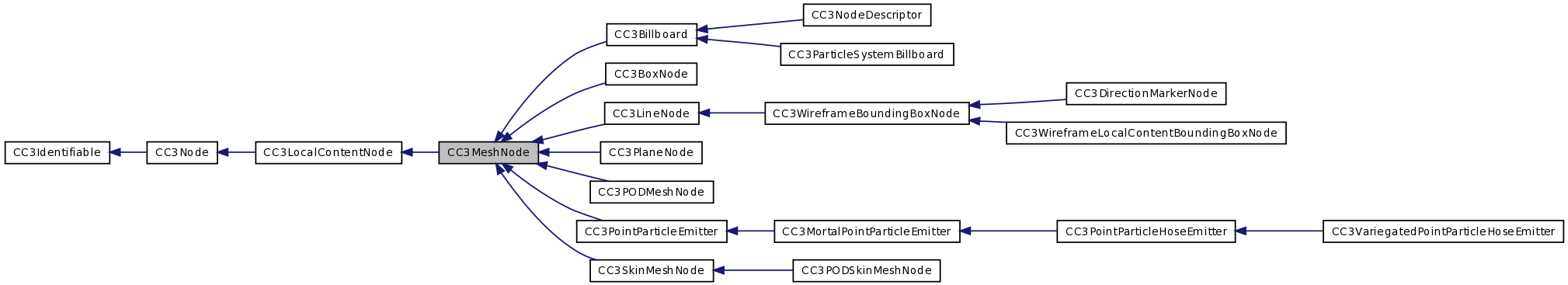
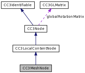
A CC3Node that draws a 3D mesh. More...
#import <CC3MeshNode.h>
Detailed Description
A CC3Node that draws a 3D mesh.
This class forms the base of all visible 3D mesh models in the 3D world.
CC3MeshNode is a type of CC3Node, and will often participate in a structural node assembly. An instance can be the child of another node, and the mesh node itself can have child nodes.
CC3MeshNodes encapsulate a CC3Mesh instance, and can also encapsulate either a CC3Material instance, or a pure color. The CC3Mesh instance contains the mesh vertex data. The CC3Material instance describes the material and texture properties covering the mesh, which are affected by lighting conditions. Alternately, instead of a material, the mesh may be colored by a single pure color via the pureColor property.
There are a number of populateAs... parametric population methods available in the CC3MeshNode (ParametricShapes) category extension. These methods can be used to populate the vertices of the mesh contained in a new mesh node to create interesting and useful parametric shapes and surfaces.
When this node is drawn, it delegates to the mesh instance to render the mesh vertices. If a material is defined, before drawing the mesh, it delegates to the material to configure the covering of the mesh. If no material is defined, the node establishes its pure color before rendering the mesh. The pure color is only used if the node has no material attached. And the pure color may in turn be overridden by the mesh data if vertex coloring is in use.
Each CC3MeshNode can have only one material or pure color. For large, complicated meshes that are covered by more than one material, or colored with more than one color, the mesh must be broken into smaller meshes, each of which are covered by a single material or color. These smaller sub-meshes are sometimes referred to as "vertex groups". Each such sub-mesh is then wrapped in its own CC3MeshNode instance, along with the material that covers that sub-mesh.
These CC3MeshNode instances can then be added as child nodes to a single parent CC3Node instance. This parent CC3Node can then be moved, rotated and scaled, and all of its child nodes will transform in sync. The assembly will behave and be seen as a single object.
When the mesh is set in the mesh property, the CC3MeshNode instance creates and builds a CC3NodeBoundingVolume instance from the mesh data, and sets it into its boundingVolume property.
When a copy is made of a CC3MeshNode instance using the copy method, a copy is made of the material, but the mesh is simply assigned by reference, and is not copied. The result is that the the new and original nodes will have different materials, but will share the same mesh. This design avoids creating multiple copies of volumnious and static mesh data when creating copies of nodes.
Normally, the front faces of a mesh are displayed, and the back faces are culled and not displayed. You can change this behaviour if you need to be changing the values of the shouldCullFrontFaces and shouldCullBackFaces properties. An example might be if you wanted to show the back-side of a planar sign, or if you wanted to show the inside faces of a skybox.
However, be aware that culling is a significant performance-improving technique. You should avoid disabling backface culling except where specifically needed for visual effect. And when you do, if you only need the back faces, turn on front face culling for that mesh by setting the shouldCullFrontFaces property to YES.
Member Function Documentation
| - (void) alignInvertedTextures |
Aligns the texture coordinates of the mesh with the textures held in the material.
The texture coordinates are aligned assuming that the texture is inverted in the Y-direction. Certain texture formats are inverted during loading, and this method can be used to compensate.
This method can be useful when the width and height of the textures in the material are not a power-of-two. Under iOS, when loading a texture that is not a power-of-two, the texture will be converted to a size whose width and height are a power-of-two. The result is a texture that can have empty space on the top and right sides. If the texture coordinates of the mesh do not take this into consideration, the result will be that only the lower left of the mesh will be covered by the texture.
When this occurs, invoking this method will adjust the texture coordinates of the mesh to map to the original width and height of the texturesa.
If the mesh is using multi-texturing, this method will adjust the texture coordinates array for each texture unit, using the corresponding texture for that texture unit in the specified material.
Care should be taken when using this method, as it changes the actual vertex data. This method should only be invoked once on any mesh, and it may cause mapping conflicts if the same mesh is shared by other CC3MeshNodes that use different textures.
This method will also invoke the superclass behaviour to invoke the same method on each child node.
To adjust the texture coordinates of only a single mesh, without adjusting the texture coordinates of any descendant nodes, invoke the alignWithInvertedTexturesIn: method of the CC3Mesh held in this mesh node. To adjust the texture coordinates of only a single texture coordinates array within the mesh, invoke the alignWithInvertedTexture: method on the appropriate instance of CC3VertexTextureCoordinates.
Implements CC3Node.
| - (void) alignTextures |
Aligns the texture coordinates of the mesh with the textures held in the material.
This method can be useful when the width and height of the textures in the material are not a power-of-two. Under iOS, when loading a texture that is not a power-of-two, the texture will be converted to a size whose width and height are a power-of-two. The result is a texture that can have empty space on the top and right sides. If the texture coordinates of the mesh do not take this into consideration, the result will be that only the lower left of the mesh will be covered by the texture.
When this occurs, invoking this method will adjust the texture coordinates of the mesh to map to the original width and height of the textures.
If the mesh is using multi-texturing, this method will adjust the texture coordinates array for each texture unit, using the corresponding texture for that texture unit in the specified material.
Care should be taken when using this method, as it changes the actual vertex data. This method should only be invoked once on any mesh, and it may cause mapping conflicts if the same mesh is shared by other CC3MeshNodes that use different textures.
This method will also invoke the superclass behaviour to invoke the same method on each child node.
To adjust the texture coordinates of only a single mesh, without adjusting the texture coordinates of any descendant nodes, invoke the alignWithTexturesIn: method of the CC3Mesh held in this mesh node. To adjust the texture coordinates of only a single texture coordinates array within the mesh, invoke the alignWithTexture: method on the appropriate instance of CC3VertexTextureCoordinates.
Implements CC3Node.
| - (void) drawWithVisitor: | (CC3NodeDrawingVisitor *) | visitor |
Draws the local content of this mesh node by following these steps:
- If the shouldDecorateNode property of the visitor is YES, and this node has a material, invokes the drawWithVisitor method of the material.
Otherwise, invokes the CC3Material class-side unbind method.
- Invokes the drawWithVisitor: method of the encapsulated mesh.
This method is called automatically from the transformAndDrawWithVisitor: method of this node. Usually, the application never needs to invoke this method directly.
Implements CC3Node.
| - (void) movePivotTo: | (CC3Vector) | aLocation |
Changes the mesh data so that the pivot point of the mesh will be at the specified location.
The pivot point of the mesh is the location in the local coordinate system around which all transforms are performed. A vertex at the pivot point would have local coordinates (0,0,0).
This method can be used to adjust the mesh structure to make it easier to apply transformations, by moving the origin of the transformations to a more convenient location in the mesh.
This method changes the location component of every vertex in the mesh data. This can be quite costly, and should only be performed once to adjust a mesh so that it is easier to manipulate.
Do not use this method to move your model around. Instead, use the transform properties (location, rotation and scale) of this node, and let the GL engine do the heavy lifting of transforming the mesh vertices.
Since the new mesh locations will change the bounding box of the mesh, this method invokes the rebuildBoundingVolume method on the boundingVolume of this node, to ensure that the boundingVolume encompasses the new vertex locations.
This method also ensures that the GL VBO that holds the vertex data is updated.
| - (void) movePivotToCenterOfGeometry |
Changes the mesh data so that the pivot point of the mesh will be at the center of geometry of the mesh vertices.
The pivot point of the mesh is the location in the local coordinate system around which all transforms are performed. A vertex at the pivot point would have local coordinates (0,0,0).
This method can be used to adjust the mesh structure to make it easier to apply transformations, by moving the origin of the transformations to the center of the mesh.
This method changes the location component of every vertex in the mesh data. This can be quite costly, and should only be performed once to adjust a mesh so that it is easier to manipulate.
Do not use this method to move your model around. Instead, use the transform properties (location, rotation and scale) of this node, and let the GL engine do the heavy lifting of transforming the mesh vertices.
Since the new mesh locations will change the bounding box of the mesh, this method invokes the rebuildBoundingVolume method on the boundingVolume of this node, to ensure that the boundingVolume encompasses the new vertex locations.
This method also ensures that the GL VBO that holds the vertex data is updated.
| - (void) populateAsCenteredRectangleWithSize: | (CGSize) | rectSize |
Populates this instance as a simple rectangular mesh of the specified size, centered at the origin, and laid out on the X-Y plane.
The rectangular mesh contains only one face with two triangles. The result is the same as invoking populateAsCenteredRectangleWithSize:andTessellation: with the facesPerSide argument set to {1,1}.
You can add a material or pureColor as desired to establish how the look of the rectangle.
| - (void) populateAsCenteredRectangleWithSize: | (CGSize) | rectSize | |
| andTessellation: | (ccGridSize) | facesPerSide | |
Populates this instance as a simple rectangular mesh of the specified size, centered at the origin, and laid out on the X-Y plane.
The large rectangle can be broken down into many smaller faces. Building a rectanglular surface from more than one face can dramatically improve realism when the surface is illuminated with specular lighting or a tightly focused spotlight, because increasing the face count increases the number of vertices that interact with the specular or spot lighting.
The facesPerSide argument indicates how to break this large rectangle into multiple faces. The X & Y elements of the facesPerSide argument indicate how each axis if the rectangle should be divided into faces. The total number of faces in the rectangle will therefore be the multiplicative product of the X & Y elements of the facesPerSide argument.
For example, a value of {5,5} for the facesPerSide argument will result in the rectangle being divided into 25 faces, arranged into a 5x5 grid.
You can add a material or pureColor as desired to establish how the look of the rectangle.
| - (void) populateAsCenteredRectangleWithSize: | (CGSize) | rectSize | |
| andTessellation: | (ccGridSize) | facesPerSide | |
| withTexture: | (CC3Texture *) | texture | |
| invertTexture: | (BOOL) | DEPRECATED_ATTRIBUTE | |
- Deprecated:
- Use the populateAsCenteredTexturedRectangleWithSize:andTessellation: method instead, and then use the texture property of this node to set the texture.
When using that replacement method, if your texture does not have both dimensions as power-of-two dimensions, you can use either of the alignTextures or alignInvertedTextures methods to adjust the mesh texture coordinates to make use of only the usable portion of the texture.
| - (void) populateAsCenteredRectangleWithSize: | (CGSize) | rectSize | |
| withTexture: | (CC3Texture *) | texture | |
| invertTexture: | (BOOL) | DEPRECATED_ATTRIBUTE | |
- Deprecated:
- Use the populateAsCenteredTexturedRectangleWithSize: method instead, and then use the texture property of this node to set the texture.
When using that replacement method, if your texture does not have both dimensions as power-of-two dimensions, you can use either of the alignTextures or alignInvertedTextures methods to adjust the mesh texture coordinates to make use of only the usable portion of the texture.
| - (void) populateAsCenteredTexturedRectangleWithSize: | (CGSize) | rectSize |
Populates this instance as a rectangular mesh of the specified size, centered at the origin, laid out on the X-Y plane, and that can be covered by a texture.
Use the texture property of this node to set the texture.
If your texture does not have both dimensions as power-of-two dimensions, you can use either of the alignTextures or alignInvertedTextures methods to adjust the mesh texture coordinates to make use of only the usable portion of the texture.
The rectangular mesh contains only one face with two triangles. The result is the same as invoking populateAsCenteredTexturedRectangleWithSize:andTessellation: with the facesPerSide argument set to {1,1}.
| - (void) populateAsCenteredTexturedRectangleWithSize: | (CGSize) | rectSize | |
| andTessellation: | (ccGridSize) | facesPerSide | |
Populates this instance as a rectangular mesh of the specified size, centered at the origin, laid out on the X-Y plane, and that can be covered by a texture.
Use the texture property of this node to set the texture.
If your texture does not have both dimensions as power-of-two dimensions, you can use either of the alignTextures or alignInvertedTextures methods to adjust the mesh texture coordinates to make use of only the usable portion of the texture.
The large rectangle can be broken down into many smaller faces. Building a rectanglular surface from more than one face can dramatically improve realism when the surface is illuminated with specular lighting or a tightly focused spotlight, because increasing the face count increases the number of vertices that interact with the specular or spot lighting.
The facesPerSide argument indicates how to break this large rectangle into multiple faces. The X & Y elements of the facesPerSide argument indicate how each axis if the rectangle should be divided into faces. The total number of faces in the rectangle will therefore be the multiplicative product of the X & Y elements of the facesPerSide argument.
For example, a value of {5,5} for the facesPerSide argument will result in the rectangle being divided into 25 faces, arranged into a 5x5 grid.
| - (void) populateAsLineStripWith: | (GLshort) | vertexCount | |
| vertices: | (CC3Vector *) | vertices | |
| andRetain: | (BOOL) | shouldRetainVertices | |
Populates this instance as a line strip with the specified number of vertex points.
The data for the points that define the end-points of the lines are contained within the specified vertices array. The vertices array must contain at least vertexCount elements.
The lines are specified and rendered as a strip, where each line is connected to the previous and following lines. Each line starts at the point where the previous line ended, and that point is defined only once in the vertices array. Therefore, the number of lines drawn is equal to one less than the specified vertexCount.
The shouldRetainVertices flag indicates whether the data in the vertices array should be retained by this instance. If this flag is set to YES, the data in the vertices array will be copied to an internal array that is managed by this instance. If this flag is set to NO, the data is not copied internally and, instead, a reference to the vertices data is established. In this case, it is up to you to manage the lifespan of the data contained in the vertices array.
If you are defining the vertices data dynamically in another method, you may want to set this flag to YES to have this instance copy and manage the data. If the vertices array is a static array, you can set this flag to NO.
You can add a material or pureColor as desired to establish the color of the lines. If a material is used, the appearance of the lines will be affected by the lighting conditions. If a pureColor is used, the appearance of the lines will not be affected by the lighting conditions, and the wire-frame box will always appear in the same pure, solid color, regardless of the lighting sources.
As this node is translated, rotate and scaled, the line strip will be re-oriented in 3D space.
This is a convenience method for creating a simple, but useful, shape.
| - (void) populateAsRectangleWithSize: | (CGSize) | rectSize | |
| andPivot: | (CGPoint) | pivot | |
Populates this instance as a simple rectangular mesh of the specified size, with the specified pivot point at the origin, and laid out on the X-Y plane.
The rectangular mesh contains only one face with two triangles. The result is the same as invoking populateAsRectangleWithSize:andPivot:andTessellation: with the facesPerSide argument set to {1,1}.
You can add a material or pureColor as desired to establish how the look of the rectangle.
The pivot point can be any point within the rectangle's size. For example, if the pivot point is {0, 0}, the rectangle will be laid out so that the bottom-left corner is at the origin. Or, if the pivot point is in the center of the rectangle's size, the rectangle will be laid out centered on the origin, as in the populateAsCenteredRectangleWithSize: method.
| - (void) populateAsRectangleWithSize: | (CGSize) | rectSize | |
| andPivot: | (CGPoint) | pivot | |
| andTessellation: | (ccGridSize) | facesPerSide | |
Populates this instance as a simple rectangular mesh of the specified size, with the specified pivot point at the origin, and laid out on the X-Y plane.
The large rectangle can be broken down into many smaller faces. Building a rectanglular surface from more than one face can dramatically improve realism when the surface is illuminated with specular lighting or a tightly focused spotlight, because increasing the face count increases the number of vertices that interact with the specular or spot lighting.
The facesPerSide argument indicates how to break this large rectangle into multiple faces. The X & Y elements of the facesPerSide argument indicate how each axis if the rectangle should be divided into faces. The total number of faces in the rectangle will therefore be the multiplicative product of the X & Y elements of the facesPerSide argument.
For example, a value of {5,5} for the facesPerSide argument will result in the rectangle being divided into 25 faces, arranged into a 5x5 grid.
You can add a material or pureColor as desired to establish how the look of the rectangle.
The pivot point can be any point within the rectangle's size. For example, if the pivot point is {0, 0}, the rectangle will be laid out so that the bottom-left corner is at the origin. Or, if the pivot point is in the center of the rectangle's size, the rectangle will be laid out centered on the origin, as in the populateAsCenteredRectangleWithSize method.
| - (void) populateAsRectangleWithSize: | (CGSize) | rectSize | |
| andPivot: | (CGPoint) | pivot | |
| andTessellation: | (ccGridSize) | facesPerSide | |
| withTexture: | (CC3Texture *) | texture | |
| invertTexture: | (BOOL) | DEPRECATED_ATTRIBUTE | |
- Deprecated:
- Use the populateAsCenteredTexturedRectangleWithSize:andPivot:andTessellation: method instead, and then use the texture property of this node to set the texture.
When using that replacement method, if your texture does not have both dimensions as power-of-two dimensions, you can use either of the alignTextures or alignInvertedTextures methods to adjust the mesh texture coordinates to make use of only the usable portion of the texture.
| - (void) populateAsRectangleWithSize: | (CGSize) | rectSize | |
| andPivot: | (CGPoint) | pivot | |
| withTexture: | (CC3Texture *) | texture | |
| invertTexture: | (BOOL) | DEPRECATED_ATTRIBUTE | |
- Deprecated:
- Use the populateAsTexturedRectangleWithSize:andPivot: method instead, and then use the texture property of this node to set the texture.
When using that replacement method, if your texture does not have both dimensions as power-of-two dimensions, you can use either of the alignTextures or alignInvertedTextures methods to adjust the mesh texture coordinates to make use of only the usable portion of the texture.
| - (void) populateAsSolidBox: | (CC3BoundingBox) | box |
Populates this instance as a simple rectangular box mesh from the specified bounding box, which contains two of the diagonal corners.
You can add a material or pureColor as desired to establish how the color of the box.
This is a convenience method for creating a simple, but useful shape, which can be used to create simple structures in your 3D world.
| - (void) populateAsTexturedBox: | (CC3BoundingBox) | box |
Populates this instance as a simple rectangular box mesh from the specified bounding box, which contains two of the diagonal corners of the box, and configures the mesh texture coordinates so that the entire box can be wrapped in a single texture.
Use the texture property of this node to set the texture.
Since the single texture is wrapped around all six sides of the box, the texture should have a specific layout, which you can see illustrated in the texture file BoxTexture.png.
The "front" of the box is the side that faces towards the positive-Z axis, the "top" of the box is the side that faces towards the positive-Y axis, and the "right" side of the box is the side that faces towards the positive-X axis.
For the purposes of wrapping the texture around the box, this method assumes that the natural shape of the box is a cube. The box can be created with any relative dimensions, but if it is not a cube, the texture may appear stretched or shrunk on two or more sides. The texture will still fully wrap all six sides of the box, but the texture is stretched or shrunk to fit each side according to its dimension relative to the other sides. The appearance will be as if you had started with a textured cube and then pulled one of the dimensions out further.
For higher fidelity in applying textures to non-cube boxes, so that the texture will not be stretched to fit, use the populateAsTexturedBox:withCorner: method.
If your texture does not have both dimensions as power-of-two dimensions, you can use either of the alignTextures or alignInvertedTextures methods to adjust the mesh texture coordinates to make use of only the usable portion of the texture.
Thanks to cocos3d user andyman for contributing the prototype code and texture template file for this method.
| - (void) populateAsTexturedBox: | (CC3BoundingBox) | box | |
| withCorner: | (CGPoint) | corner | |
Populates this instance as a simple rectangular box mesh from the specified bounding box, which contains two of the diagonal corners of the box, and configures the mesh texture coordinates so that the entire box can be wrapped in a single texture.
Use the texture property of this node to set the texture.
Since the single texture is wrapped around all six sides of the box, the texture should have a specific layout, which you can see illustrated in the texture file BoxTexture.png.
The "front" of the box is the side that faces towards the positive-Z axis, the "top" of the box is the side that faces towards the positive-Y axis, and the "right" side of the box is the side that faces towards the positive-X axis.
For the purposes of wrapping the texture around the box, the corner argument is used to indicate the relative dimensions of the box. Specifically, the corner argument specifies the point in the texture that is at the juncture of the "left" "front" and "bottom" sides of the texture (see the BoxTexture.png image for a better understanding of this point), and is specified as a fraction in each of the S & T dimensions of the texture. In the CGPoint that specifies the corner, the x & y elements of the CGPoint correspond to the S & T dimensions of the juncture of the "left", "front" and "bottom" sides in the texture.
Since, by definition, opposite sides of the box have the same dimensions, this single corner point identifies the S & T dimensions of all six of the sides of the box. A value of (1/4, 1/3) for the corner is used when the box is a cube. A smaller value for the x-element would move the corner to the left in the texture layout, indicating that the left and right sides are shallower than they are in a cube, and that the front and back are wider than in a cube, and vice-versa for a larger value in the x-element of the corner. Similarly for the y-element. A y-element that is smaller than 1/3, moves the corner point downwards on the texture, indicating that the bottom and top are shallower than they are in a cube, or that the front and back are higher than they are in a cube.
The two axes defined by the corner are interrelated, because the sides need to be the same depth as the top and bottom. The best way to determine the values to use in the corner is to use the measure of this point (where the "left", "front", and "bottom" sides meet) from the layout of the texture.
If your texture is not have both dimensions as power-of-two dimensions, you can use either of the alignTextures or alignInvertedTextures methods to adjust the mesh texture coordinates to make use of only the usable portion of the texture.
Thanks to cocos3d user andyman for contributing the prototype code and texture template file for this method.
| - (void) populateAsTexturedRectangleWithSize: | (CGSize) | rectSize | |
| andPivot: | (CGPoint) | pivot | |
Populates this instance as a rectangular mesh of the specified size, with the specified pivot point at the origin, laid out on the X-Y plane, and that can be covered by a texture.
Use the texture property of this node to set the texture.
If your texture does not have both dimensions as power-of-two dimensions, you can use either of the alignTextures or alignInvertedTextures methods to adjust the mesh texture coordinates to make use of only the usable portion of the texture.
The pivot point can be any point within the rectangle's size. For example, if the pivot point is {0, 0}, the rectangle will be laid out so that the bottom-left corner is at the origin. Or, if the pivot point is in the center of the rectangle's size, the rectangle will be laid out centered on the origin, as in the populateAsCenteredTexturedRectangleWithSize: method.
The rectangular mesh contains only one face with two triangles. The result is the same as invoking populateAsCenteredTexturedRectangleWithSize:andPivot:andTessellation: with the facesPerSide argument set to {1,1}.
| - (void) populateAsTexturedRectangleWithSize: | (CGSize) | rectSize | |
| andPivot: | (CGPoint) | pivot | |
| andTessellation: | (ccGridSize) | facesPerSide | |
Populates this instance as a rectangular mesh of the specified size, with the specified pivot point at the origin, laid out on the X-Y plane, and that can be covered by a texture.
Use the texture property of this node to set the texture.
If your texture does not have both dimensions as power-of-two dimensions, you can use either of the alignTextures or alignInvertedTextures methods to adjust the mesh texture coordinates to make use of only the usable portion of the texture.
The pivot point can be any point within the rectangle's size. For example, if the pivot point is {0, 0}, the rectangle will be laid out so that the bottom-left corner is at the origin. Or, if the pivot point is in the center of the rectangle's size, the rectangle will be laid out centered on the origin, as in the populateAsCenteredTexturedRectangleWithSize: method.
The large rectangle can be broken down into many smaller faces. Building a rectanglular surface from more than one face can dramatically improve realism when the surface is illuminated with specular lighting or a tightly focused spotlight, because increasing the face count increases the number of vertices that interact with the specular or spot lighting.
The facesPerSide argument indicates how to break this large rectangle into multiple faces. The X & Y elements of the facesPerSide argument indicate how each axis if the rectangle should be divided into faces. The total number of faces in the rectangle will therefore be the multiplicative product of the X & Y elements of the facesPerSide argument.
For example, a value of {5,5} for the facesPerSide argument will result in the rectangle being divided into 25 faces, arranged into a 5x5 grid.
| - (void) populateAsWireBox: | (CC3BoundingBox) | box |
Populates this instance as a wire-frame box with the specified dimensions.
You can add a material or pureColor as desired to establish the color of the lines of the wire-frame. If a material is used, the appearance of the lines will be affected by the lighting conditions. If a pureColor is used, the appearance of the lines will not be affected by the lighting conditions, and the wire-frame box will always appear in the same pure, solid color, regardless of the lighting sources.
As this node is translated, rotate and scaled, the wire-frame box will be re-oriented in 3D space.
This is a convenience method for creating a simple, but useful, shape.
| - (void) repeatTexture: | (ccTex2F) | repeatFactor |
Configures the mesh so that a texture applied to this mesh will be repeated the specified number of times across the mesh, in each dimension.
The repeatFactor argument contains two numbers, corresponding to how many times in each dimension the texture should be repeated.
As an example, a value of (1, 2) for the repeatValue indicates that the texture should repeat twice vertically, but not repeat horizontally.
When a texture is repeated, the corresponding side of the texture covering this mesh must have a length that is a power-of-two, otherwise the padding added by iOS to convert it to a power-of-two length internally will be visible in the repeating pattern across the mesh.
For a side that is not repeating, the corresponding side of the texture covering this mesh does not require a length that is a power-of-two.
The textureParameters property of any texture covering this mesh should include the GL_REPEAT setting in each of its texture wrap components that correspond to a repeatFactor greater than one. The GL_REPEAT setting is the default setting for CC3Texture.
For example, if you want to repeat your texture twice in one dimension, but only once in the other, then you would use a repeatFactor of (1, 2) or (2, 1). For the side that is repeating twice, the length of that side of the texture must be a power-of-two. But the other side may have any dimension. The textureParameters property of the CC3Texture should include the GL_REPEAT setting for the corresponding texture dimension.
If your texture requires aligning with the mesh (typically if one of the texture dimensions is not a power-of-two), you should invoke either the alignTextures or alignInvertedTextures method before invoking this method.
In the example above, you would invoke one of those methods before invoking this method, to first align the mesh with that non-power-of-two side.
The dimensions of the repeatFactor are independent of the size derived from the texture by the alignTextures or alignInvertedTextures methods. A value of 1.0 for an element in the specified repeatFactor will automatically take into consideration the adjustment made to the mesh by those methods, and will display only the part of the texture defined by them.
You can specify a fractional value for either of the components of the repeatFactor to expand the texture in that dimension so that only part of the texture appears in that dimension, while potentially repeating multiple times in the other dimension.
| - (void) setTextureRectangle: | (CGRect) | aRect | |
| forTextureUnit: | (GLuint) | texUnit | |
Sets the textureRectangle property from the texture coordinates that are mapping the specified texture unit index.
See the notes for the textureRectangle property of this class for an explanation of the use of this property.
| - (void) setVertexColor4B: | (ccColor4B) | aColor | |
| at: | (GLsizei) | index | |
Sets the color element at the specified index in the vertex data to the specified value.
The index refers to vertices, not bytes. The implementation takes into consideration the elementStride and elementOffset properties to access the correct element.
When all vertex changes have been made, be sure to invoke the updateVertexColorsGLBuffer method to ensure that the GL VBO that holds the vertex data is updated.
If the releaseRedundantData method has been invoked and the underlying vertex data has been released, this method will raise an assertion exception.
| - (void) setVertexColor4F: | (ccColor4F) | aColor | |
| at: | (GLsizei) | index | |
Sets the color element at the specified index in the vertex data to the specified value.
The index refers to vertices, not bytes. The implementation takes into consideration the elementStride and elementOffset properties to access the correct element.
When all vertex changes have been made, be sure to invoke the updateVertexColorsGLBuffer method to ensure that the GL VBO that holds the vertex data is updated.
If the releaseRedundantData method has been invoked and the underlying vertex data has been released, this method will raise an assertion exception.
| - (void) setVertexIndex: | (GLushort) | vertexIndex | |
| at: | (GLsizei) | index | |
Sets the index element at the specified index in the vertex data to the specified value.
The index refers to vertices, not bytes. The implementation takes into consideration the elementStride and elementOffset properties to access the correct element.
When all vertex changes have been made, be sure to invoke the updateVertexIndicesGLBuffer method to ensure that the GL VBO that holds the vertex data is updated.
If the releaseRedundantData method has been invoked and the underlying vertex data has been released, this method will raise an assertion exception.
| - (void) setVertexLocation: | (CC3Vector) | aLocation | |
| at: | (GLsizei) | index | |
Sets the location element at the specified index in the vertex data to the specified value.
The index refers to vertices, not bytes. The implementation takes into consideration the elementStride and elementOffset properties to access the correct element.
Since the new vertex location may change the bounding box of the mesh, when all vertex changes have been made, be sure to invoke the rebuildBoundingVolume method on this node, to ensure that the boundingVolume encompasses the new vertex locations.
When all vertex changes have been made, be sure to invoke the updateVertexLocationsGLBuffer method to ensure that the GL VBO that holds the vertex data is updated.
If the releaseRedundantData method has been invoked and the underlying vertex data has been released, this method will raise an assertion exception.
| - (void) setVertexNormal: | (CC3Vector) | aNormal | |
| at: | (GLsizei) | index | |
Sets the normal element at the specified index in the vertex data to the specified value.
The index refers to vertices, not bytes. The implementation takes into consideration the elementStride and elementOffset properties to access the correct element.
When all vertex changes have been made, be sure to invoke the updateVertexNormalsGLBuffer method to ensure that the GL VBO that holds the vertex data is updated.
If the releaseRedundantData method has been invoked and the underlying vertex data has been released, this method will raise an assertion exception.
| - (void) setVertexTexCoord2F: | (ccTex2F) | aTex2F | |
| at: | (GLsizei) | index | |
Sets the texture coordinate element at the specified index in the vertex data, at the commonly used texture unit zero, to the specified texture coordinate value.
This is a convenience method that delegates to the setVertexTexCoord2F:forTextureUnit:at: method, passing in zero for the texture unit index.
The index refers to vertices, not bytes. The implementation takes into consideration the elementStride and elementOffset properties to access the correct element.
When all vertex changes have been made, be sure to invoke the updateVertexTextureCoordinatesGLBuffer method to ensure that the GL VBO that holds the vertex data is updated.
If the releaseRedundantData method has been invoked and the underlying vertex data has been released, this method will raise an assertion exception.
| - (void) setVertexTexCoord2F: | (ccTex2F) | aTex2F | |
| at: | (GLsizei) | index | |
| forTextureUnit: | (GLuint) | DEPRECATED_ATTRIBUTE | |
- Deprecated:
- Use the setVertexTexCoord2F:forTextureUnit:at: method instead,
| - (void) setVertexTexCoord2F: | (ccTex2F) | aTex2F | |
| forTextureUnit: | (GLuint) | texUnit | |
| at: | (GLsizei) | index | |
Sets the texture coordinate element at the specified index in the vertex data, at the specified texture unit index, to the specified texture coordinate value.
The index refers to vertices, not bytes. The implementation takes into consideration the elementStride and elementOffset properties to access the correct element.
When all vertex changes have been made, be sure to invoke the updateVertexTextureCoordinatesGLBufferForTextureUnit: method to ensure that the GL VBO that holds the vertex data is updated.
If the releaseRedundantData method has been invoked and the underlying vertex data has been released, this method will raise an assertion exception.
| - (CGRect) textureRectangleForTextureUnit: | (GLuint) | texUnit |
Returns the textureRectangle property from the texture coordinates that are mapping the specified texture unit index.
See the notes for the textureRectangle property of this class for an explanation of the use of this property.
| - (void) updateVertexColorsGLBuffer |
Updates the GL engine buffer with the vertex color data in this mesh.
| - (void) updateVertexIndicesGLBuffer |
Updates the GL engine buffer with the vertex index data in this mesh.
| - (void) updateVertexLocationsGLBuffer |
Updates the GL engine buffer with the vertex location data in this mesh.
| - (void) updateVertexNormalsGLBuffer |
Updates the GL engine buffer with the vertex normal data in this mesh.
| - (void) updateVertexTextureCoordinatesGLBuffer |
Updates the GL engine buffer with the vertex texture coord data from texture unit zero in this mesh.
| - (void) updateVertexTextureCoordinatesGLBufferForTextureUnit: | (GLuint) | texUnit |
Updates the GL engine buffer with the vertex texture coord data from the specified texture unit in this mesh.
| - (ccColor4B) vertexColor4BAt: | (GLsizei) | index |
Returns the color element at the specified index from the vertex data.
The index refers to vertices, not bytes. The implementation takes into consideration the elementStride and elementOffset properties to access the correct element.
If the releaseRedundantData method has been invoked and the underlying vertex data has been released, this method will raise an assertion exception.
| - (ccColor4F) vertexColor4FAt: | (GLsizei) | index |
Returns the color element at the specified index from the vertex data.
The index refers to vertices, not bytes. The implementation takes into consideration the elementStride and elementOffset properties to access the correct element.
If the releaseRedundantData method has been invoked and the underlying vertex data has been released, this method will raise an assertion exception.
| - (GLushort) vertexIndexAt: | (GLsizei) | index |
Returns the index element at the specified index from the vertex data.
The index refers to vertices, not bytes. The implementation takes into consideration the elementStride and elementOffset properties to access the correct element.
If the releaseRedundantData method has been invoked and the underlying vertex data has been released, this method will raise an assertion exception.
| - (CC3Vector) vertexLocationAt: | (GLsizei) | index |
Returns the location element at the specified index from the vertex data.
The index refers to vertices, not bytes. The implementation takes into consideration the elementStride and elementOffset properties to access the correct element.
If the releaseRedundantData method has been invoked and the underlying vertex data has been released, this method will raise an assertion exception.
| - (CC3Vector) vertexNormalAt: | (GLsizei) | index |
Returns the normal element at the specified index from the vertex data.
The index refers to vertices, not bytes. The implementation takes into consideration the elementStride and elementOffset properties to access the correct element.
If the releaseRedundantData method has been invoked and the underlying vertex data has been released, this method will raise an assertion exception.
| - (ccTex2F) vertexTexCoord2FAt: | (GLsizei) | index |
Returns the texture coordinate element at the specified index from the vertex data at the commonly used texture unit zero.
This is a convenience method that is equivalent to invoking the vertexTexCoord2FForTextureUnit:at: method, with zero as the texture unit index.
The index refers to vertices, not bytes. The implementation takes into consideration the elementStride and elementOffset properties to access the correct element.
If the releaseRedundantData method has been invoked and the underlying vertex data has been released, this method will raise an assertion exception.
| - (ccTex2F) vertexTexCoord2FAt: | (GLsizei) | index | |
| forTextureUnit: | (GLuint) | DEPRECATED_ATTRIBUTE | |
- Deprecated:
- Use the vertexTexCoord2FForTextureUnit:at: method instead,
| - (ccTex2F) vertexTexCoord2FForTextureUnit: | (GLuint) | texUnit | |
| at: | (GLsizei) | index | |
Returns the texture coordinate element at the specified index from the vertex data at the specified texture unit index.
The index refers to vertices, not bytes. The implementation takes into consideration the elementStride and elementOffset properties to access the correct element.
If the releaseRedundantData method has been invoked and the underlying vertex data has been released, this method will raise an assertion exception.
Member Data Documentation
- (GLenum) depthFunction [protected] |
The depth function used by the GL engine when comparing the Z-distance of this node against previously drawn content.
This property only has effect if the shouldDisableDepthTest property is set to NO.
This property must be set to one of the following values:
- GL_LESS - the content of this node will be drawn if it is closer to the camera than previously drawn content.
- GL_LEQUAL - the content of this node will be drawn if it is at least as close to the camera as previously drawn content.
- GL_EQUAL - the content of this node will be drawn if it is exactly as close to the camera as previously drawn content.
- GL_GEQUAL - the content of this node will be drawn if it is at least as far away from the camera as previously drawn content.
- GL_GREATER - the content of this node will be drawn if it is farther away from the camera than previously drawn content.
- GL_NOTEQUAL - the content of this node will be drawn if it is not exactly as close to the camera as previously drawn content.
- GL_ALWAYS - the content of this node will always be drawn
- GL_NEVER - the content of this node will not be drawn
The initial value of this property is GL_LEQUAL. In most cases, to draw an accurate scene, this value is the most suitable. However, some special cases, including some particle emitters, may benefit from the use of one of the other depth functions.
Setting this value sets the same property on all descendant nodes.
Querying this property returns the value of this property from the first descendant mesh node, or will return GL_NEVER if no mesh node are found in the descendants of this node.
Implements CC3Node.
- (CC3NormalScaling) normalScalingMethod [protected] |
Specifies the method to be used to scale vertex normals after they have been transformed during vertex drawing.
Normal vectors should have a unit length. Since normals are vectors in the local coordinate system of the node, they are transformed into world and eye coordinates during drawing.
During transformation, there are several factors that might distort the normal vector:
- If the normals started out not being of unit length, they will generally be transformed into vectors that are not of unit length.
- If the transforms are not rigid, and include scaling, even normals that have unit length in object space will end up shorter or longer than unit length in eye space.
- If the transform scaling is not uniform, the normals will shear, and end up shorter or longer than unit length.
Normals that are not of unit length, or are sheared, will cause portions of the objects to appear lighter or darker after transformation, or will cause specular highlights to actually be dark, distorting the overall look of the material covering the mesh.
The GL engine can be instructed to compensate for these transforms by setting this property as follows:
- kCC3NormalScalingNone: No compensating scaling is performed on the normals after they have been transformed. This has the highest performance, but will not adjust the normals if they have been scaled. Use this option if you know that the normals will not be significantly scaled during transformation.
- kCC3NormalScalingRescale: Uses the modelview matrix to scale all normals by the inverse of the node's overall scaling. This does have a processing cost, but is much faster than using kCC3NormalScalingNormalize. However, it is not as accurate if significantly non-uniform scaling has been applied to the node.
- kCC3NormalScalingNormalize: Normalizes each norml vector independently. This is the most accurate method, but is also, by far, the most computationally expensive. Use this method only if selecting one of the other options does not give you the results that you expect.
- kCC3NormalScalingAutomatic: Chooses the most appropriate method based on the scaling that has been applied to the node. If no scaling has been applied to the node, kCC3NormalScalingNone will be used. If only uniform scaling has been applied to the node, kCC3NormalScalingRescale will be used. If non-uniform scaling has been applied to the node, then kCC3NormalScalingNormalize will be used.
The initial value of this property is kCC3NormalScalingAutomatic. You can generally leave this property at this default value unless you are not getting the results that you expect.
Setting this property sets the corresponding property in all descendant nodes, and affects the processing of normals in all vertex meshes contained in all descendant nodes.
Querying this property returns the value of this property from the first descendant mesh node, or will return kCC3NormalScalingNone if no mesh node are found in the descendants of this node.
Implements CC3Node.
- (BOOL) shouldCullBackFaces [protected] |
Indicates whether the back faces should be culled on the meshes contained in descendants of this node.
The initial value is YES, indicating that back faces will not be displayed. You can set this property to NO if you have reason to display the back faces of the mesh (for instance, if you have a rectangular plane and you want to show both sides of it).
Since the normal of the face points out the front face, back faces interact with light the same way the front faces do, and will appear luminated by light that falls on the front face, much like a stained-glass window. This may not be the affect that you are after, and for some lighting conditions, instead of disabling back face culling, you might consider creating a second textured front face, placed back-to-back with the original front face.
Be aware that culling improves performance, so this property should be set to NO only when specifically needed for visual effect, and only on the meshes that need it.
Setting this value sets the same property on all descendant nodes.
Querying this property returns NO if any of the descendant mesh nodes have this property set to NO. Initially, and in most cases, all mesh nodes have this property set to YES.
For more information about this use of this property, see the class notes for the CC3MeshNode class.
Implements CC3Node.
- (BOOL) shouldCullFrontFaces [protected] |
Indicates whether the front faces should be culled on the meshes contained in descendants of this node.
The initial value is NO. Normally, you should leave this property with the initial value, unless you have a specific need not to display the front faces.
Setting this value sets the same property on all descendant nodes.
Querying this property returns YES if any of the descendant mesh nodes have this property set to YES. Initially, and in most cases, all mesh nodes have this property set to NO.
For more information about this use of this property, see the class notes for the CC3MeshNode class.
Implements CC3Node.
- (BOOL) shouldDisableDepthMask [protected] |
Indicates whether this instance will disable the GL depth mask while drawing the content of this node.
When the depth mask is disabled, drawing activity will not write to the depth buffer.
If this property is set to NO, the Z-distance of this node will be compared against previously drawn content, and the drawing of this node will update the depth buffer, so that subsequent drawing will take into consideration the Z-distance of this node.
If this property is set to YES, the Z-distance of this node will still be compared against previously drawn content, but the drawing of this node will NOT update the depth buffer, and subsequent drawing will NOT take into consideration the Z-distance of this node.
This property only has effect if the shouldDisableDepthTest property is set to NO.
In most cases, to draw an accurate scene, we want depth testing to be performed at all times, and this property is usually set to NO. However, there are some occasions where it is useful to disable writing to the depth buffer during the drawing of a node. One notable situation is with particle systems, where temporarily disabling the depth mask will avoid Z-fighting between individual particles.
The initial value of this property is NO, indicating that the GL depth mask will not be disabled during the drawing of this node, and the depth buffer will be updated during the drawing of this node.
Setting this value sets the same property on all descendant nodes.
Querying this property returns YES if any of the descendant mesh nodes have this property set to YES, otherwise returns NO.
Implements CC3Node.
- (BOOL) shouldDisableDepthTest [protected] |
Indicates whether this instance will disable the GL depth test while drawing the content of this node.
When the depth test is disabled, the Z-distance of this node will not be compared against previously drawn content, and drawing activity will not write to the depth buffer.
If this property is set to NO, the Z-distance of this node will be compared against previously drawn content, and the drawing of this node will update the depth buffer, so that subsequent drawing will take into consideration the Z-distance of this node.
If this property is set to YES, the Z-distance of this node will not be compared against previously drawn content and this node will be drawn over all previously drawn content. In addition, the drawing of this node will not update the depth buffer, with the result that subsequent object drawing will not take into consideration the Z-distance of this node.
In most cases, to draw an accurate scene, we want depth testing to be performed at all times, and this property is usually set to NO. However, there are some occasions where it is useful to disable depth testing during the drawing of a node. One notable situation is with particle systems, where temporarily disabling depth testing may help avoid Z-fighting between individual particles.
The initial value of this property is NO, indicating that the GL depth tesing will not be disabled during the drawing of this node, and the depth buffer will be updated during the drawing of this node.
Setting this value sets the same property on all descendant nodes.
Querying this property returns YES if any of the descendant mesh nodes have this property set to YES, otherwise returns NO.
Implements CC3Node.
- (BOOL) shouldUseClockwiseFrontFaceWinding [protected] |
Indicates whether the edge-widing algorithm used by the GL engine to determine which face of a triangle is the front face should use clockwise winding.
If this property is set to YES, the front face of all triangles in the mesh of this node will be determined using clockwise winding of the edges. If this property is set to NO, the front face of all triangles in the mesh of this node will be determined using counter-clockwise winding of the edges.
The initial value of this property is NO, indicating that the OpenGL-standard counter-clockwise winding will be used by the GL engine to determine the front face of all triangles in the mesh of this node. Unless you have a reason to change this value, you should leave it at the initial value.
Setting this value sets the same property on all descendant nodes.
Querying this property returns YES if any of the descendant mesh nodes have this property set to YES, otherwise returns NO.
Implements CC3Node.
- (BOOL) shouldUseSmoothShading [protected] |
Indicates whether the shading of the faces of the mesh of this node should be smoothly shaded, using color interpolation between vertices.
If this property is set to YES, the color of each pixel in any face in the mesh of this node will be interpolated from the colors of all three vertices of the face, using the distance of the pixel to each vertex as the means to interpolate. The result is a smooth gradient of color across the face.
If this property is set to NO, the color of all pixels in any face in the mesh of this node will be determined by the color at the third vertex of the face. All pixels in the face will be painted in the same color.
The initial value is YES. For realistic rendering, you should leave this property with the initial value, unless you have a specific need to render flat color across each face in the mesh, such as to deliberately create a cartoon-like effect on the model.
Setting this value sets the same property on all descendant nodes.
Querying this property returns NO if any of the descendant mesh nodes have this property set to NO. Initially, and in most cases, all mesh nodes have this property set to YES.
Implements CC3Node.
Property Documentation
- (ccColor4F) ambientColor [read, write, assign] |
The ambient color of the material of this mesh node.
Material color is initially set to kCC3DefaultMaterialColorAmbient. If this instance has no material, this property will return kCCC4FBlackTransparent.
The value of this property is also affected by changes to the color and opacity properties. See the notes for those properties for more information.
Implements CC3Node.
- (ccBlendFunc) blendFunc [read, write, assign] |
Implementation of the CCBlendProtocol blendFunc property.
This is a convenience property that gets and sets both the sourceBlend and destinationBlend properties of the material used by this node using a single structure. Changes to this property is also passed along to any child nodes. Querying this property returns {GL_ONE, GL_ZERO} if this node has no material.
Implements CC3Node.
- (ccColor3B) color [read, write, assign] |
Implementation of the CCRGBAProtocol color property.
Querying this property returns the RGB components of the material's diffuseColor property, or of this node's pureColor property if this node has no material. In either case, the RGB values are converted from the floating point range (0 to 1), to the byte range (0 to 255).
When setting this property, the RGB values are each converted to a floating point number between 0 and 1, and are set into both the ambientColor and diffuseColor properties of this node's material, and the pureColor property of this node. The alpha of each of those properties remains unchanged.
Setting this property also sets the same property on all descendant nodes.
Implements CC3Node.
- (CC3MeshModel* meshModel) DEPRECATED_ATTRIBUTE [read, write, retain] |
- Deprecated:
- CC3MeshModel renamed to CC3Mesh.
Use mesh property instead.
- (ccColor4F) diffuseColor [read, write, assign] |
The diffuse color of the material of this mesh node.
Material color is initially set to kCC3DefaultMaterialColorDiffuse. If this instance has no material, this property will return kCCC4FBlackTransparent.
The value of this property is also affected by changes to the color and opacity properties. See the notes for those properties for more information.
Implements CC3Node.
- (ccColor4F) emissionColor [read, write, assign] |
The emission color of the material of this mesh node.
Material color is initially set to kCC3DefaultMaterialColorEmission. If this instance has no material, this property will return kCCC4FBlackTransparent.
The value of this property is also affected by changes to the opacity property. See the notes for the opacity property for more information.
Implements CC3Node.
- (CC3Vector) globalLightLocation [read, write, assign] |
When this mesh node is textured with a DOT3 bump-map (normal map), this property indicates the location, in the global coordinate system, of the light that is illuminating the node.
This global light location is tranformed from a loction in the global coordinate system to a direction in the local coordinate system of this node. This local direction is then applied to the texture of this node, where it interacts with the normals stored in the bump-map texture to determine surface illumination.
This property only needs to be set, and will only have effect when set, when one of the textures of this node is configured as a bump-map. Set the value of this property to the globalLocation of the light source. Bump-map textures may interact with only one light source.
When setting this property, this implementation also sets the same property in all child nodes. When reading this property, this implementation returns a value if this node contains a texture configured for bump-mapping, or the value of the same property from the first descendant node that is a CC3MeshNode and that contains a texture configured for bump-mapping. Otherwise, this implementation returns kCC3VectorZero.
Implements CC3Node.
- (BOOL) isOpaque [read, write, assign] |
Indicates whether the material of this mesh node is opaque.
If this node has a material, returns the value of the same property on the material. If this node has no material, return YES if the alpha component of the pureColor property is 1.0, otherwise returns NO.
Setting this property sets the same property in the material and in all descendants, and sets the alpha component of the pureColor property to 1.0.
See the notes for this property on CC3Material for more information on how this property interacts with the other material properties.
Setting this property should be thought of as a convenient way to switch between the two most common types of blending combinations. For finer control of blending, set specific blending properties on the CC3Material instance directly, and avoid making changes to this property.
Implements CC3Node.
- (CC3Material *) material [read, write, retain] |
The material covering this mesh node.
- (CC3Mesh *) mesh [read, write, retain] |
The mesh that holds the vertex data for this mesh node.
When this property is set, if this node has a boundingVolume, it is forced to rebuild itself, otherwise, if this node does not have a boundingVolume, a default bounding volume is created from the mesh.
- (GLubyte) opacity [read, write, assign] |
Implementation of the CCRGBAProtocol opacity property.
Querying this property returns the alpha component of the material's diffuseColor property, or of this node's pureColor property if this node has no material. In either case, the RGB values are converted from the floating point range (0 to 1), to the byte range (0 to 255).
When setting this property, the value is converted to a floating point number between 0 and 1, and is set into all of the ambientColor, diffuseColor, specularColor, and emissionColor properties of this node's material, and the pureColor property of this node The RGB components of each of those properties remains unchanged.
Setting this property also sets the same property on all descendant nodes.
See the notes for this property on CC3Material for more information on how this property interacts with the other material properties.
Setting this property should be thought of as a convenient way to switch between the two most common types of blending combinations. For finer control of blending, set specific blending properties on the CC3Material instance directly, and avoid making changes to this property.
Implements CC3Node.
- (int) podMaterialIndex [read, write, assign] |
The index of the material in the POD file used by this node.
- (ccColor4F) pureColor [read, write, assign] |
The pure, solid color used to paint the mesh if no material is established for this node.
This color is not not be affected by the lighting conditions. The mesh will always appear in the same pure, solid color, regardless of the lighting sources.
- (BOOL) shouldDrawLowAlpha [read, write, assign] |
Indicates whether alpha testing should be used to determine if pixels with lower alpha values should be drawn.
Setting or reading the value of this property will set or return the value of the same property on the material covering this mesh.
If the value of this property is set to YES, each pixel will be drawn regardless of the value of its alpha component. If the value of this property is set to NO, the value of the alpha component of each pixel will be compared against the value in the alphaTestReference property of the material, and only those pixel alpha values that are greater than that reference value will be drawn. You can set the value of the alphaTestReference property of the material to determine the cutoff level.
The initial value of this property is YES, indicating that pixels with lower alpha values will be drawn.
For most situations, alpha testing is not necessary, and you can leave the value of this property set to YES. Alpha testing can sometimes be useful when drawing overlapping objects that each contain transparency, and it is not possible to rely only on drawing order and depth testing to mediate whether a pixel should be drawn.
- (BOOL) shouldUseLighting [read, write, assign] |
If this value is set to YES, current lighting conditions will be taken into consideration when drawing colors and textures, and the material ambientColor, diffuseColor, specularColor, emissionColor, and shininess properties will have effect.
If this value is set to NO, lighting conditions will be ignored when drawing colors and textures, and the material emissionColor will be applied to the mesh surface without regard to lighting. Blending will still occur, but the other material aspects, including ambientColor, diffuseColor, specularColor, and shininess will be ignored. This is useful for a cartoon effect, where you want a pure color, or the natural colors of the texture, to be included in blending calculations, without having to arrange lighting, or if you want those colors to be displayed in their natural values despite current lighting conditions.
Setting the value of this property sets the same property in the contained material. Reading the value of this property returns the value of the same property in the contained material.
The initial value of this property is YES.
Implements CC3Node.
- (ccColor4F) specularColor [read, write, assign] |
The specular color of the material of this mesh node.
Material color is initially set to kCC3DefaultMaterialColorSpecular. If this instance has no material, this property will return kCCC4FBlackTransparent.
The value of this property is also affected by changes to the opacity property. See the notes for the opacity property for more information.
Implements CC3Node.
- (CC3Texture*) texture [read, write, retain] |
When the material covering this mesh contains a single texture, this property references that texture.
When multi-texturing is in use, and the material holds more than one texture, this property references the texture that will be processed by GL texture unit zero.
This property is a convenience. It simply delegates to the same property on the material covering this mesh node.
When setting this property, if a material does not yet exist in this mesh node, a new material will be created and the texture will be attached to it.
- (CGRect) textureRectangle [read, write, assign] |
Defines the rectangular area of the textures, for all texture units, that should be mapped to the mesh used by this node.
This property facilitates the use of sprite-sheets, where the mesh is covered by a small fraction of a larger texture. This technique has many uses, including animating a texture onto a mesh, where each section of the full texture is really a different frame of a texture animation, or simply loading one larger texture and using parts of it to texture many different meshes.
The dimensions of this rectangle are taken as fractional portions of the full area of the texture. Therefore, a rectangle with zero origin, and unit size ((0.0, 0.0), (1.0, 1.0)) indicates that the mesh should be covered with the complete texture.
A rectangle of smaller size, and/or a non-zero origin, indicates that the mesh should be covered by a fractional area of the texture. For example, a rectangular value for this property with origin at (0.5, 0.5), and size of (0.5, 0.5) indicates that only the top-right quarter of the texture will be used to cover this mesh.
The bounds of the texture rectangle must fit within a unit rectangle. Both the bottom-left and top-right corners must lie between zero and one in both the X and Y directions.
The dimensions of the rectangle in this property are independent of adjustments made by the alignTextures and alignInvertedTextures methods. A unit rectangle value for this property will automatically take into consideration the adjustment made to the mesh by those methods, and will display only the part of the texture defined by them. Rectangular values for this property that are smaller than the unit rectangle will be relative to the displayable area defined by alignTextures and alignInvertedTextures.
As an example, if the alignWithTexturesIn: method was used to limit the mesh to using only 80% of the texture (perhaps when using a non-POT texture), and this property was set to a rectangle with origin at (0.5, 0.0) and size (0.5, 0.5), the mesh will be covered by the bottom-right quarter of the usable 80% of the overall texture.
This property affects all texture units used by this mesh, to query or change this property for a single texture unit only, use the textureRectangleForTextureUnit: and setTextureRectangle:forTextureUnit: methods.
The initial value of this property is a rectangle with origin at zero, and unit size, indicating that the mesh will be covered with the complete usable area of the texture.
- (GLsizei) vertexCount [read, assign] |
Returns the number of vertices in this mesh.
The documentation for this class was generated from the following file: